Scale Detail
Pictures showing some of the detailing on this model
|
|
|
 |
 |
 |
 |
 |
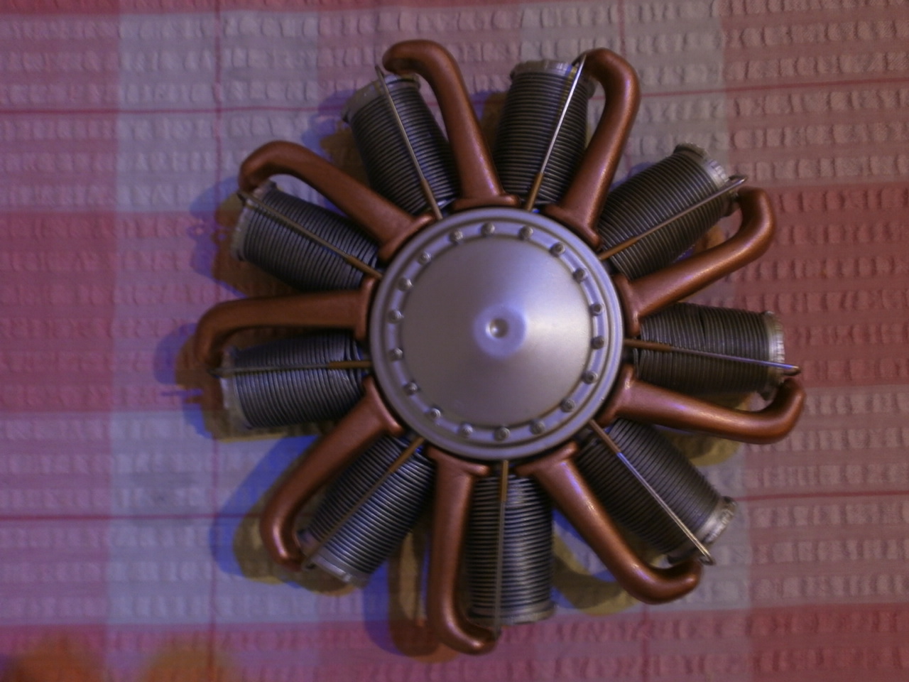 |
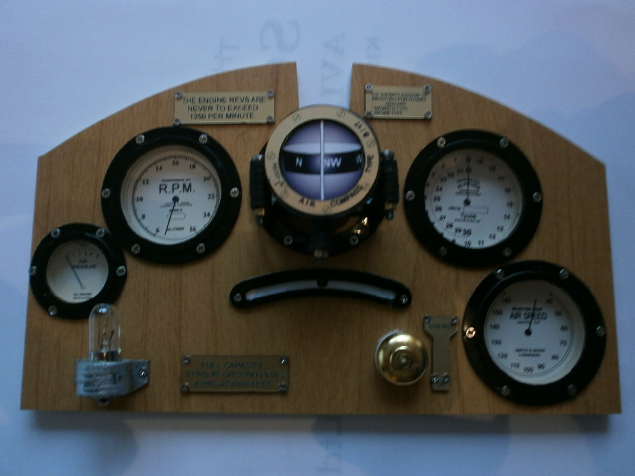
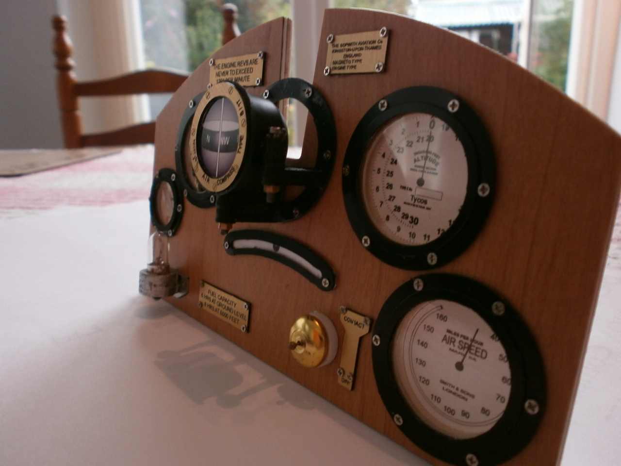
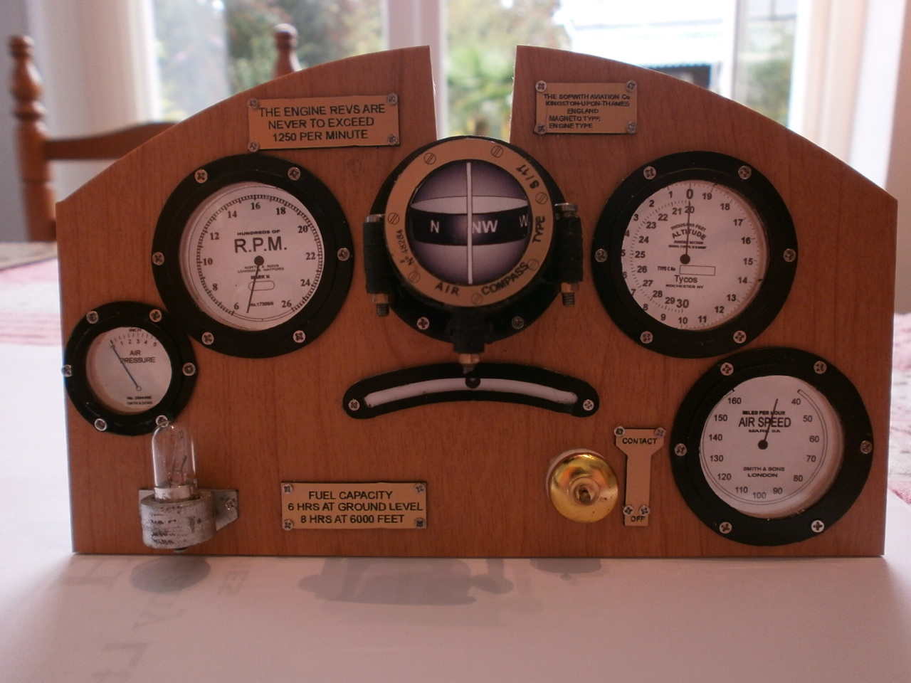
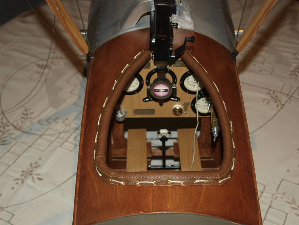
PUP DASHBOARD 1/4 SCALE KIT AVAILABLE FROM MICK REEVES MODEL
This took two evenings to complete but well worth the time spent
 |
 |
 |
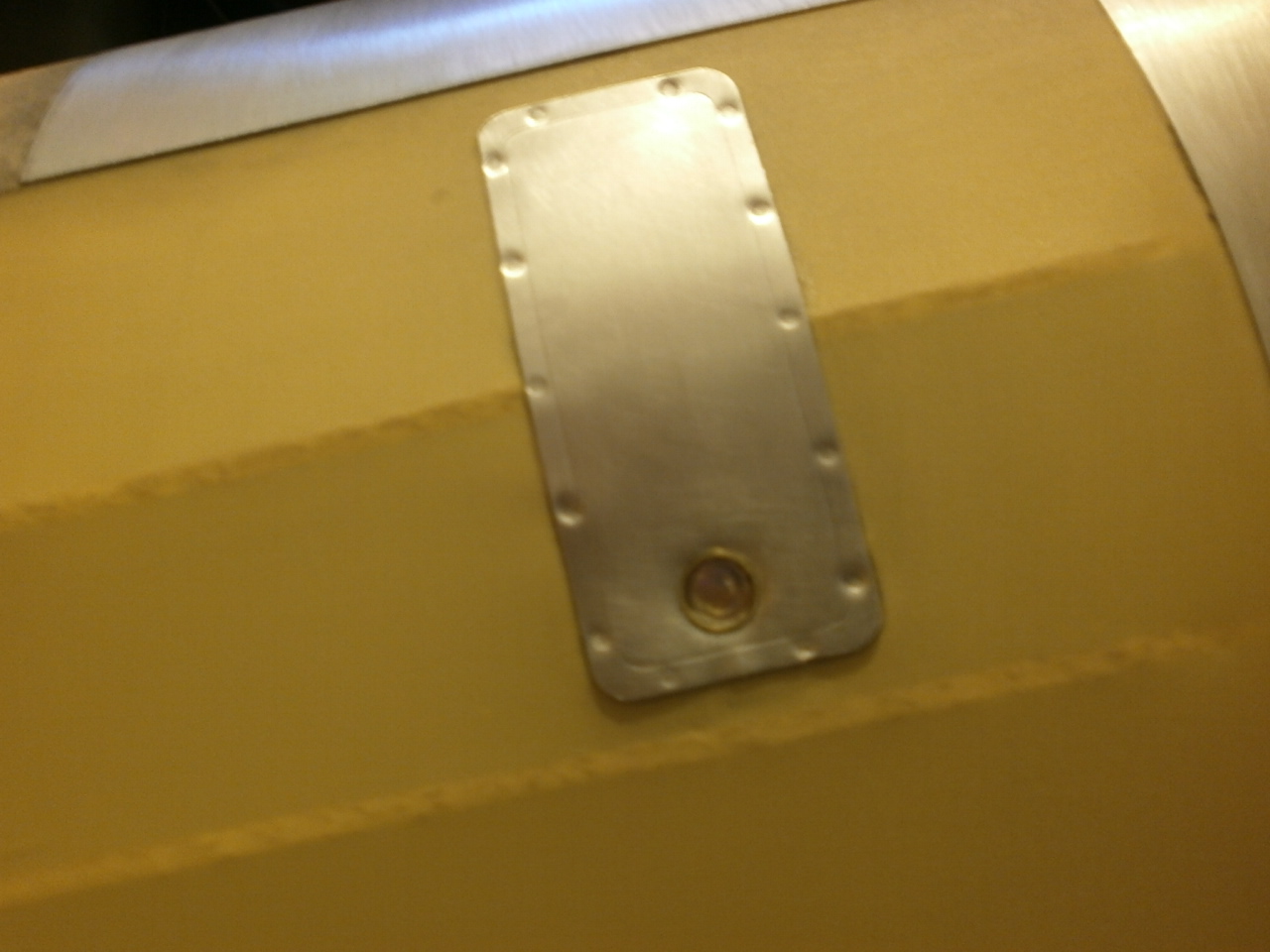
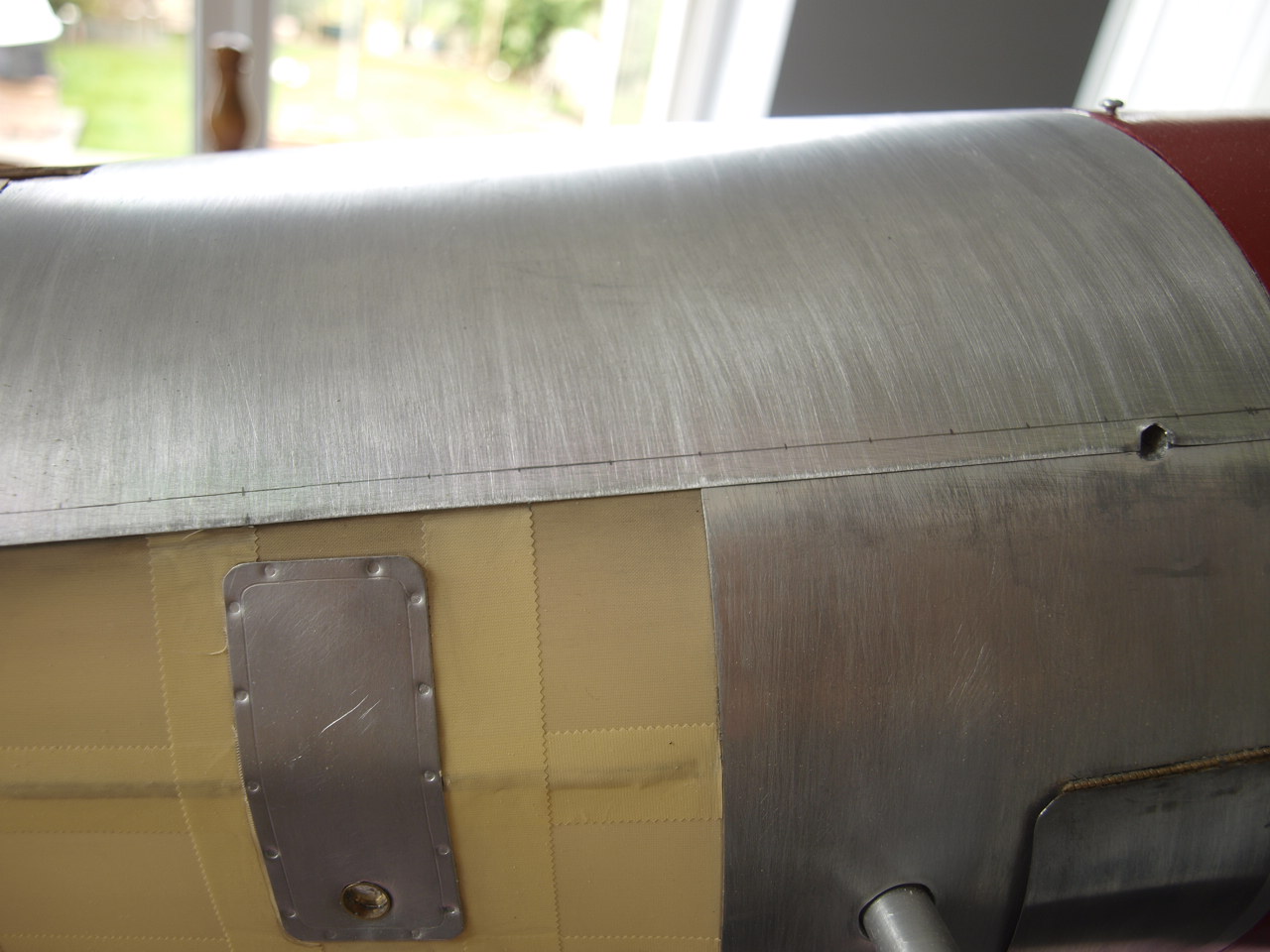
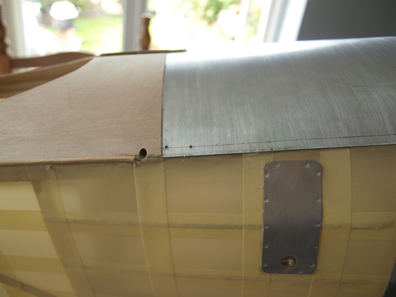
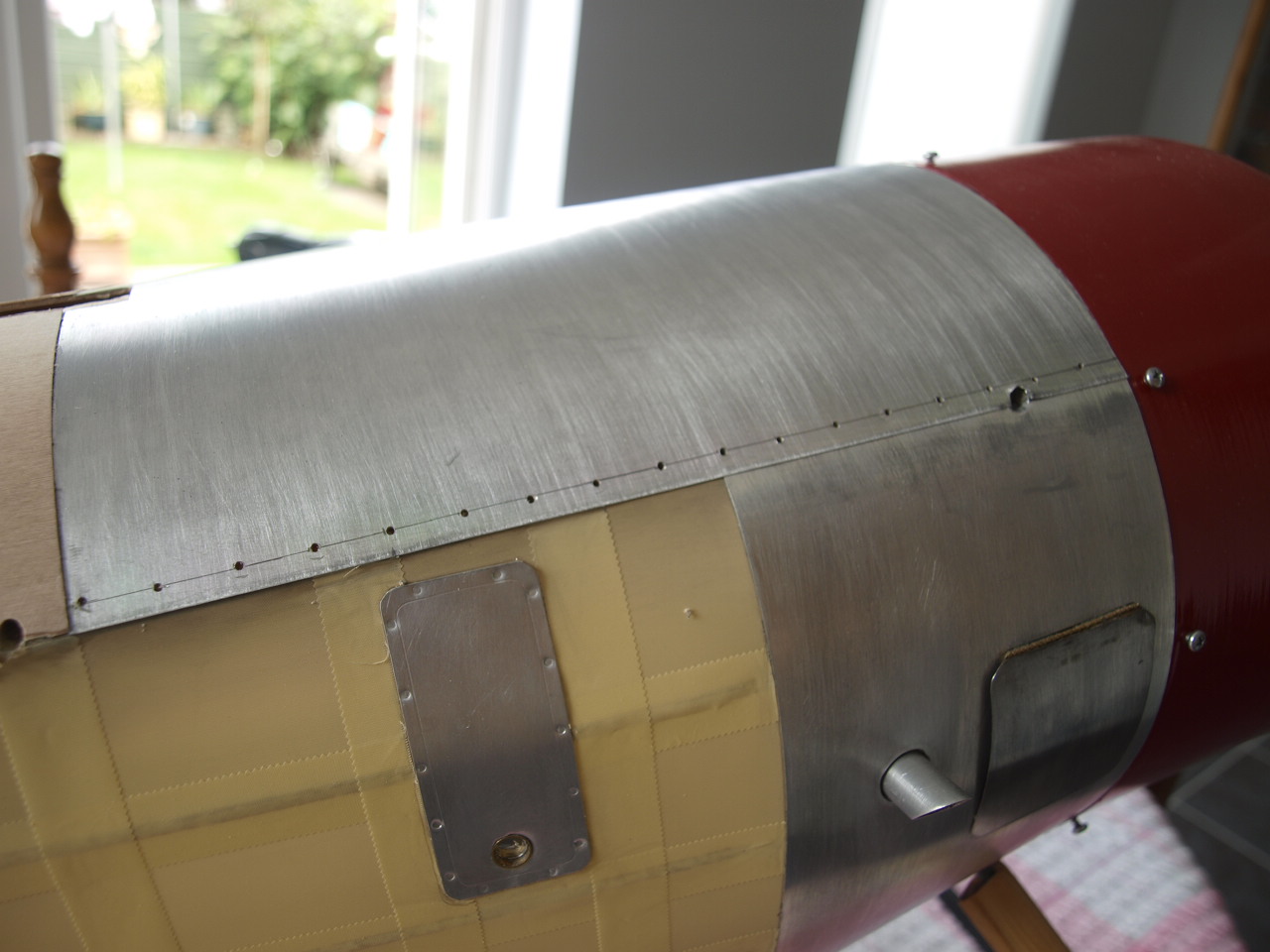
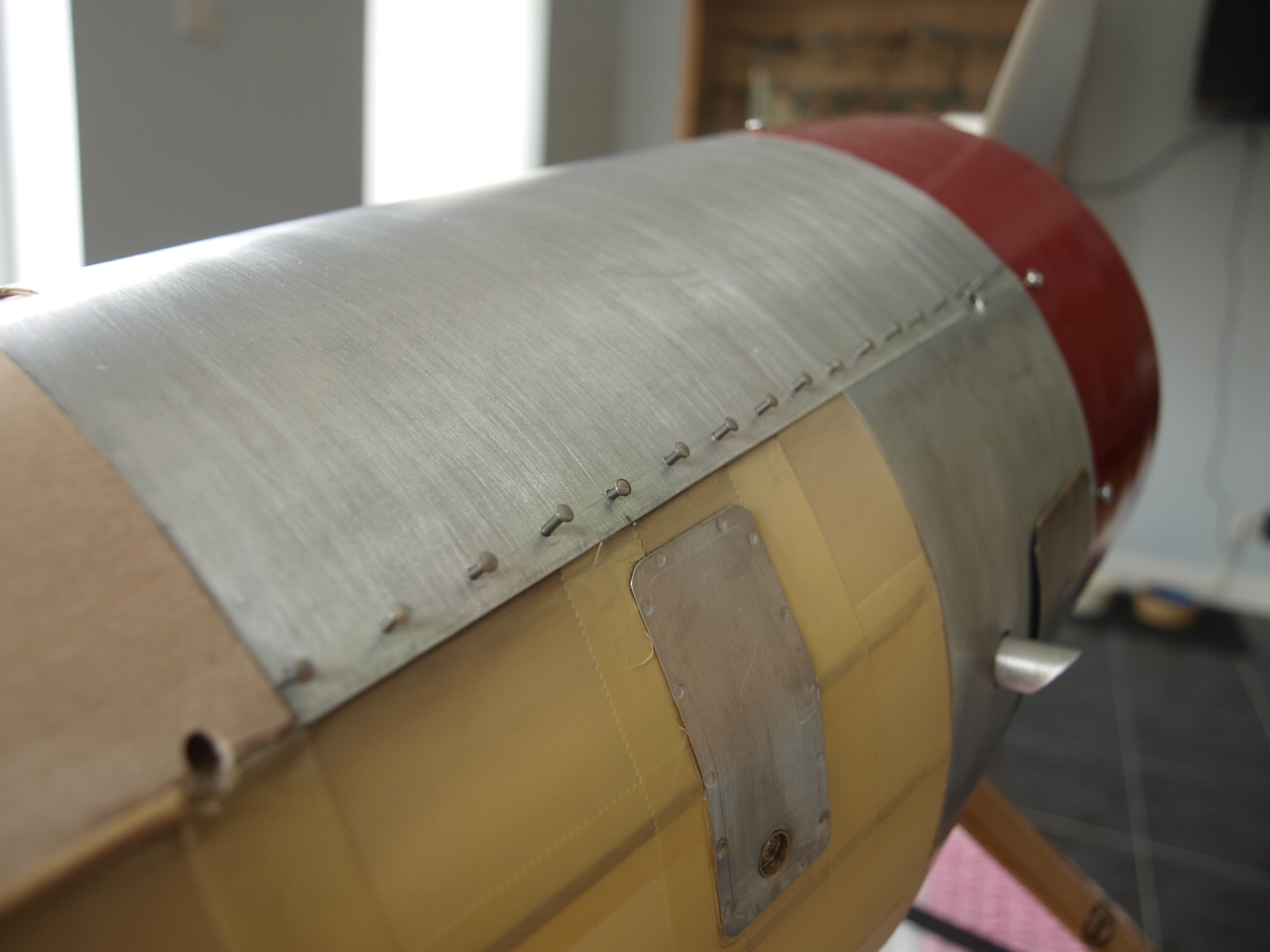
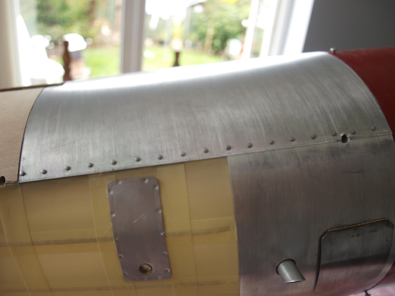
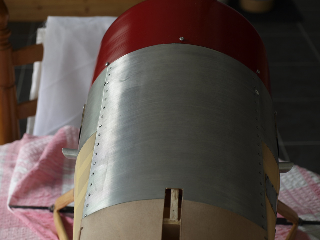
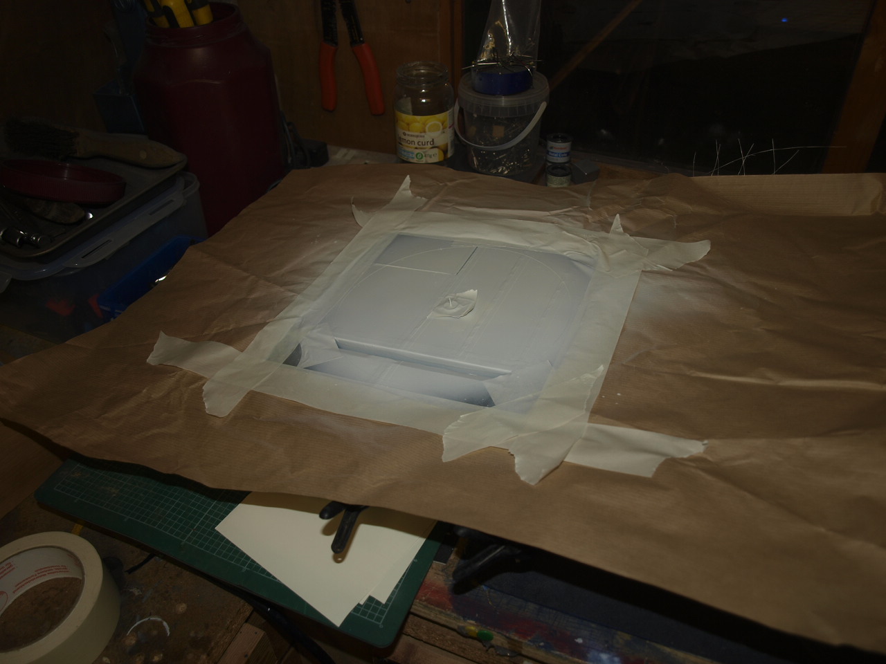
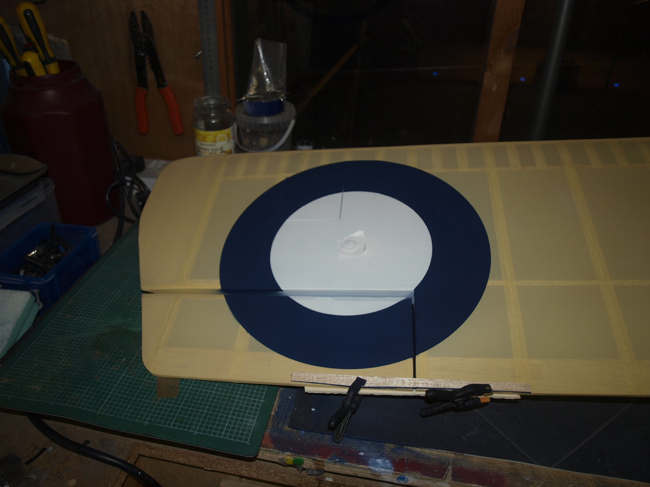
The following pictures showing the riveting
along the top panel. First of all a line is drawn horizontally along the top
panel, approximately 5mm up from the panel edge.
Then along this marks are placed at 13.5mm intervals. Once marked holes are
drilled through the plate with a 1.5mm drill bit.
Into these are placed aluminium rivets with a 1/16 head. They are then glued
into place using Zap medium super glue being careful not to get any runs over
the panel.
There you have it a nice scale feature.
 |
 |
 |
 |
 |
 |
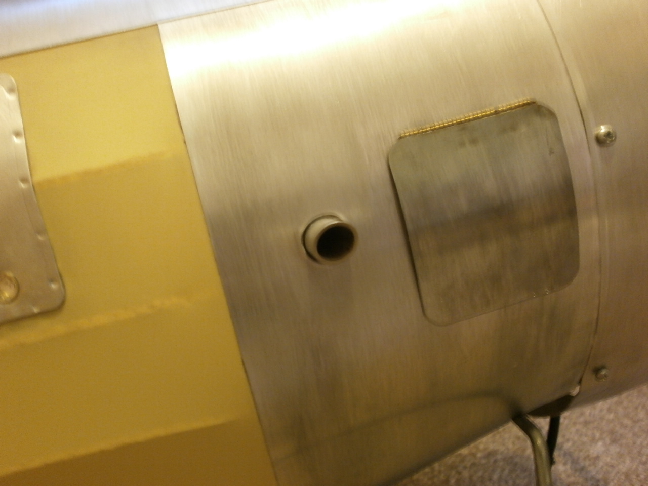
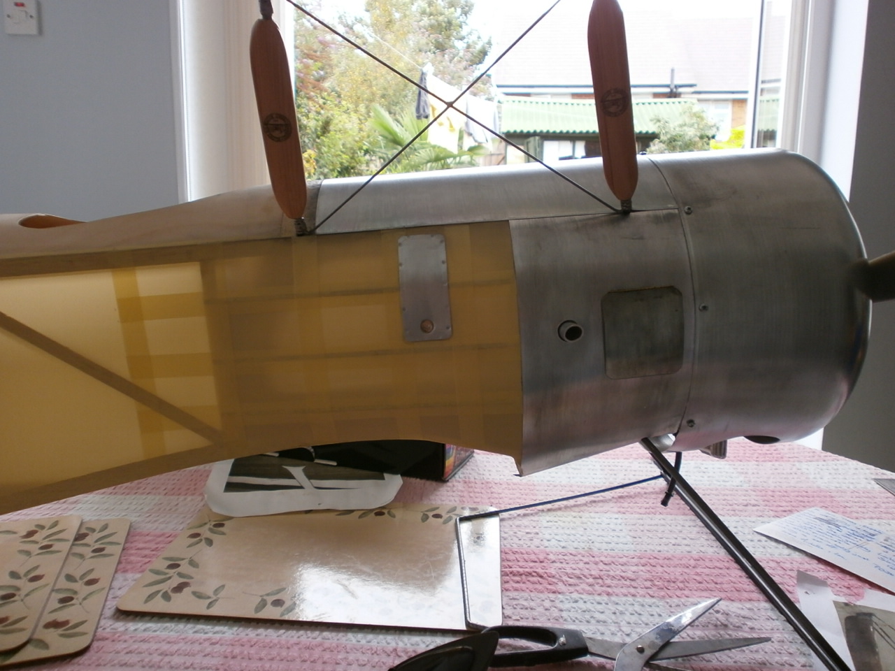
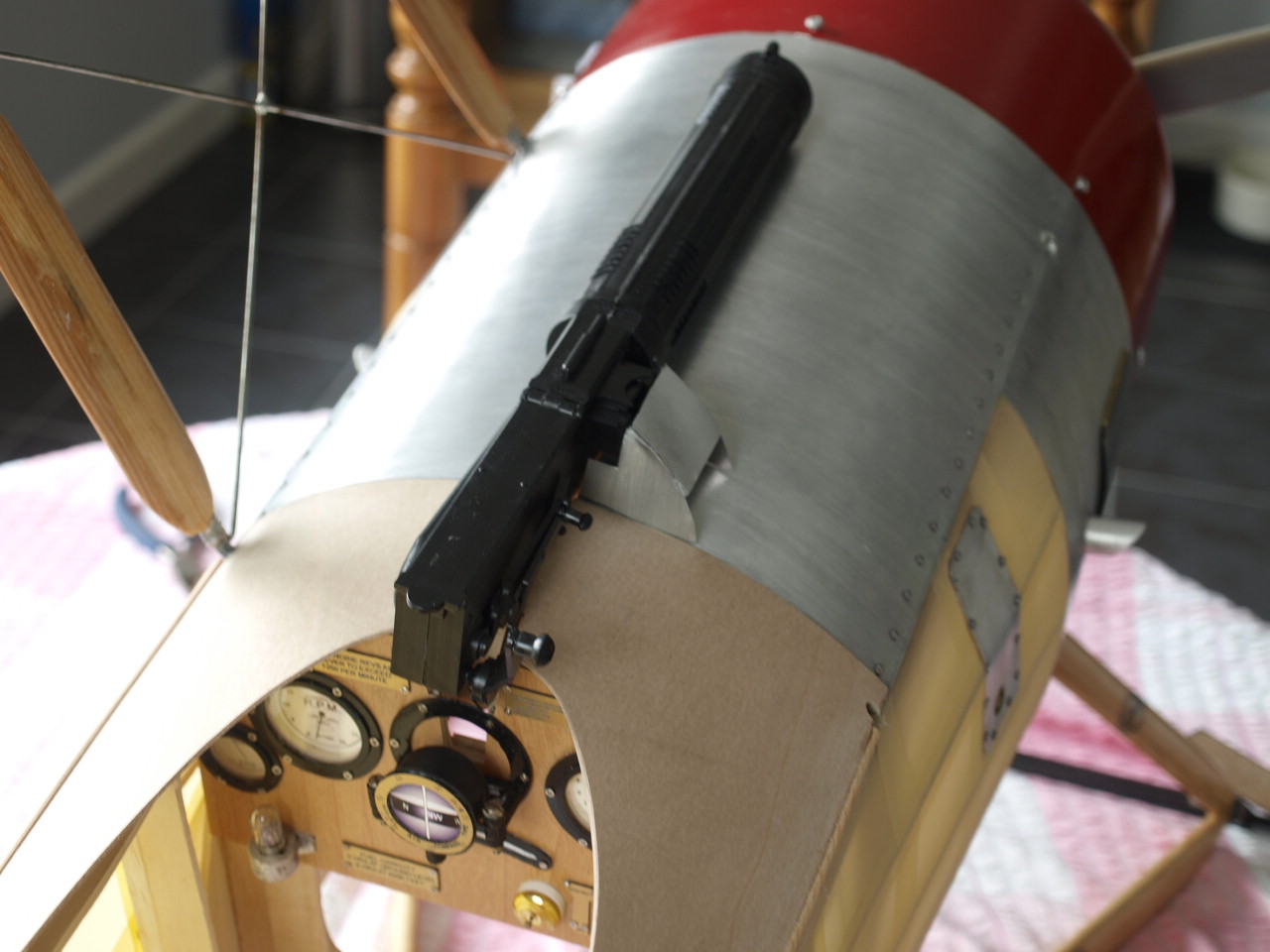
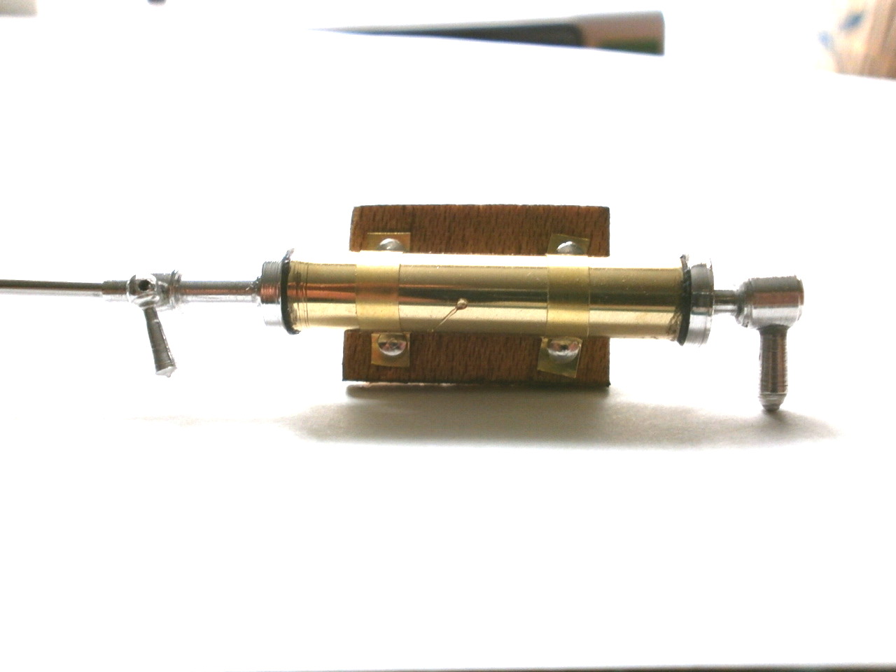
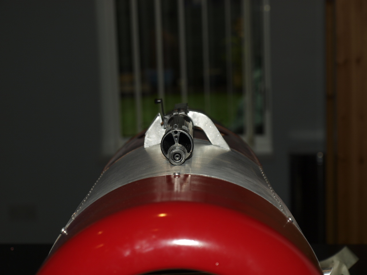
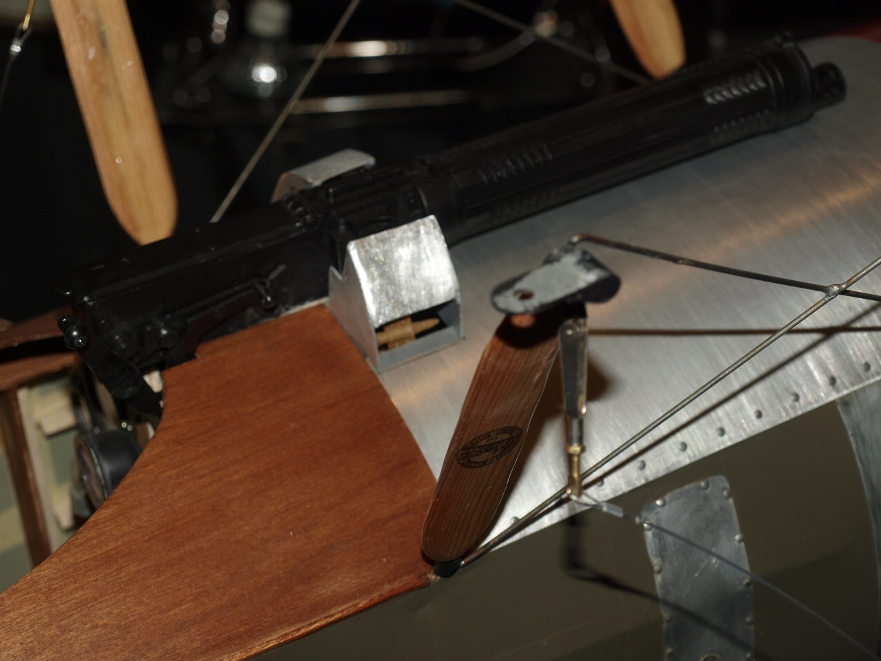
Below work started on installing the 1/4 scale Vickers machine gun picture 1 and my attempt at replicating the fuel tank air pressurisation manual air pump
 |
 |
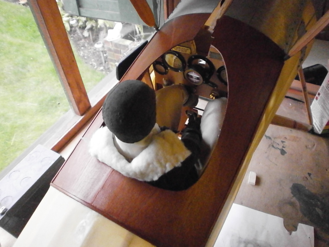
Below are a couple of pictures of the cockpit seat although not a 100% scale a reasonable representation I hope.
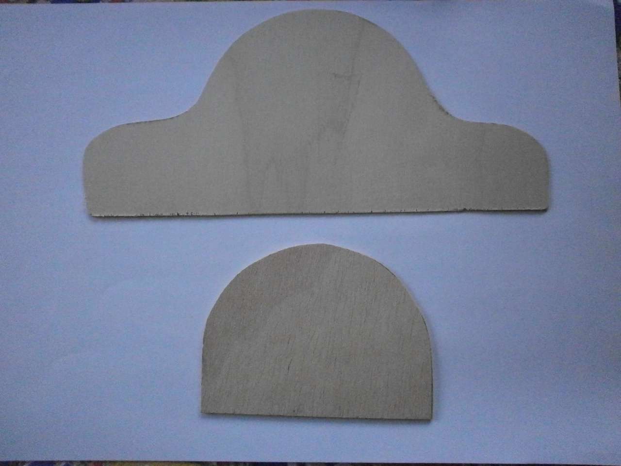 Ply seat sections cut to shape |
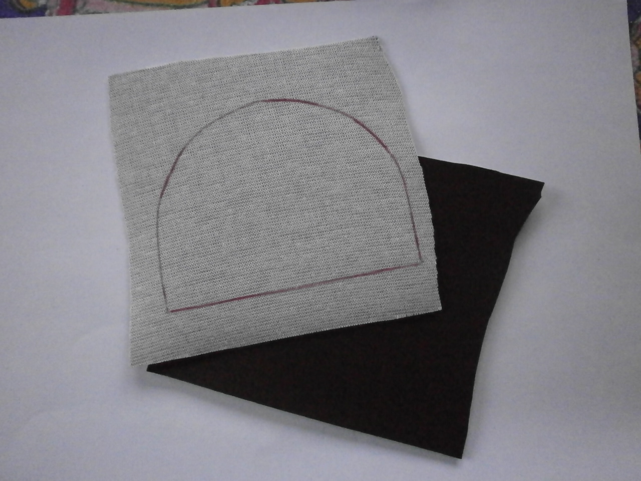 Seat cushion before sowing |
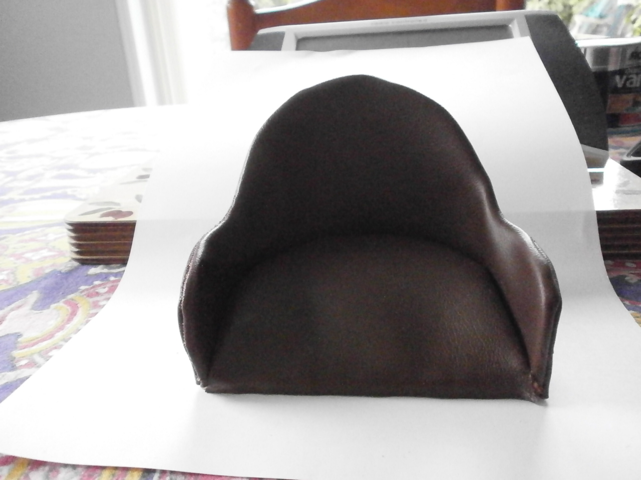
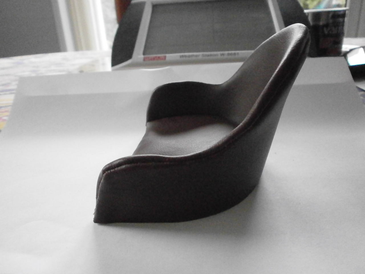
Below finished seat
 |
 |
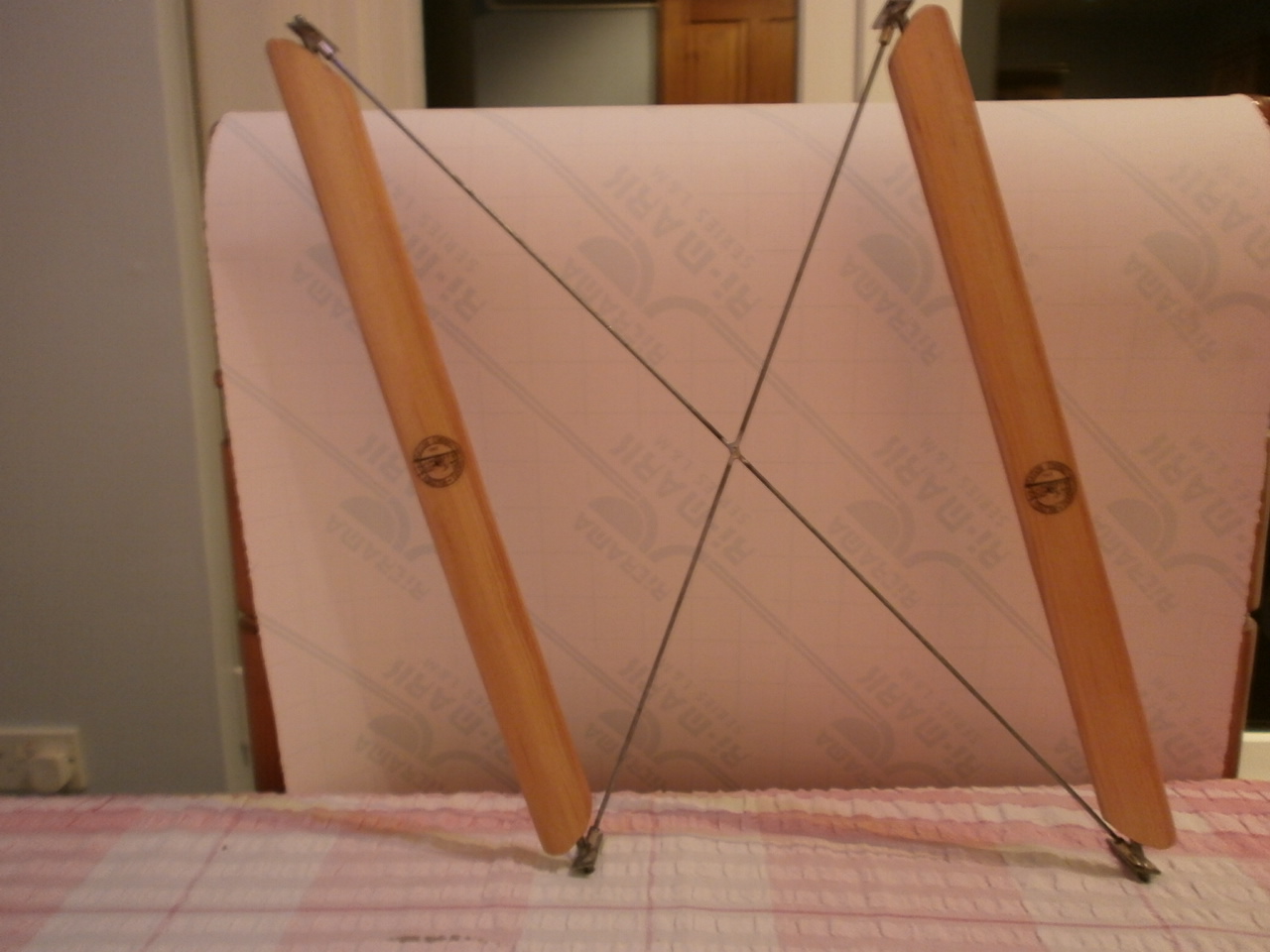
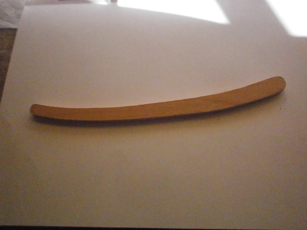
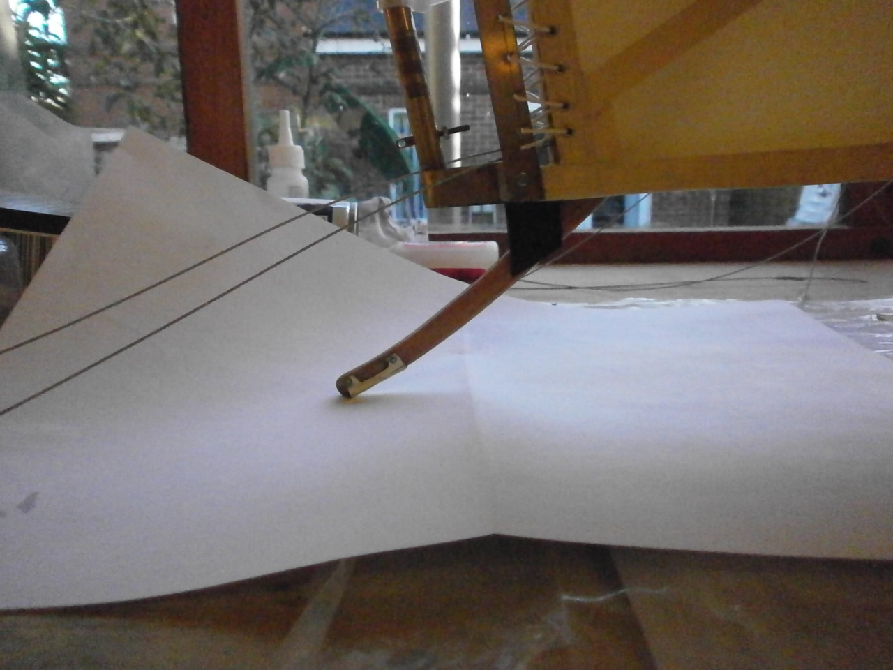
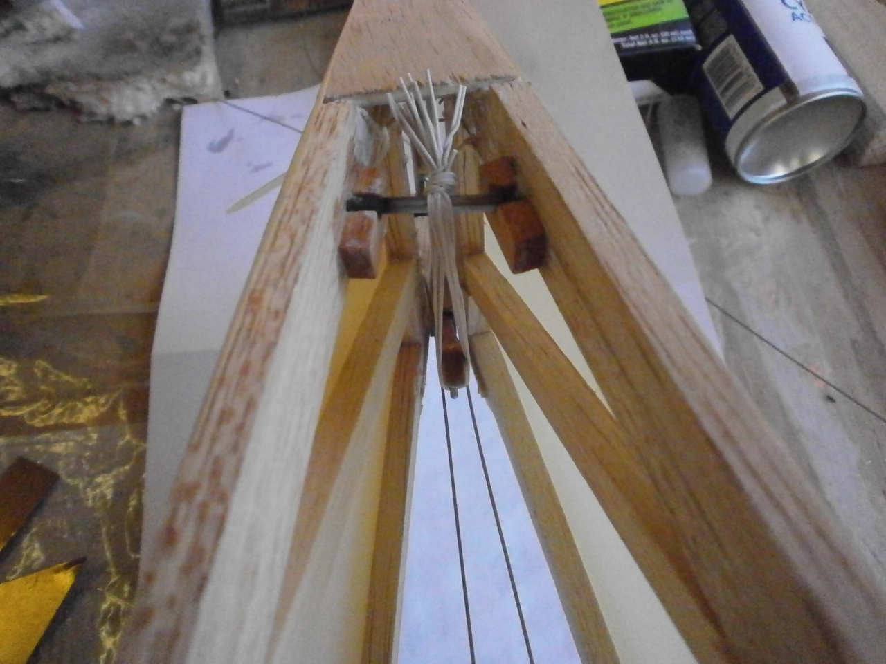
Tail skid
The following couple of pictures showing the Tail skid and skid in place. This operates pretty much in the same way as the full size sprung with bungee elastic.
 |
 |
 |
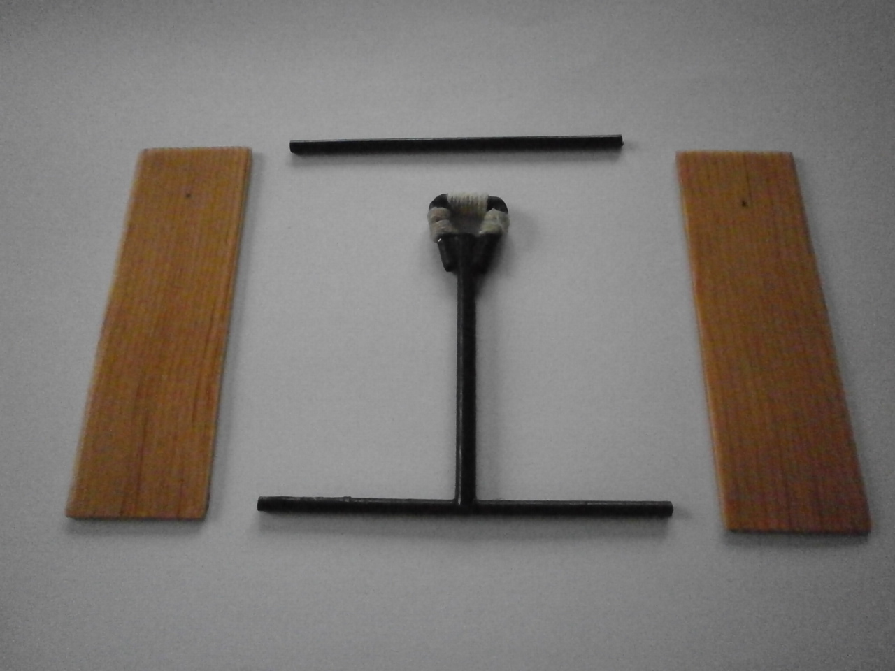
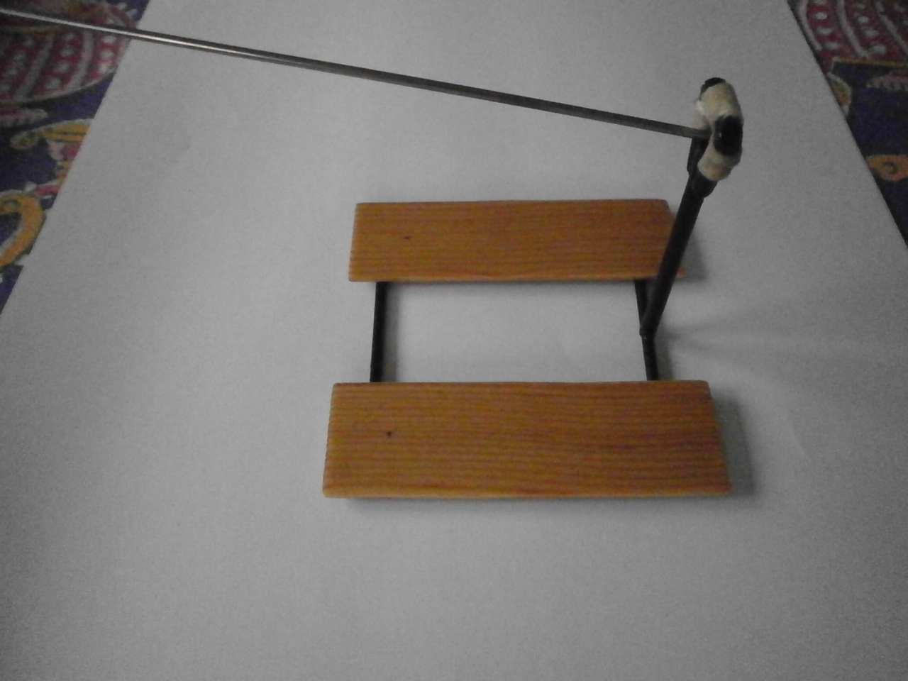
Joy Stick and Foot Boards
The following pictures below showing the individual parts that make up the joy stick and foot boards. The joy stick is made up from brass tube sections soldered together.
This is then painted and the handle rapped with thread as per the full size. The foot boards are cut from spruce strip and the vanished. These parts are then assembled together ready for installation to the cockpit
 |
 |
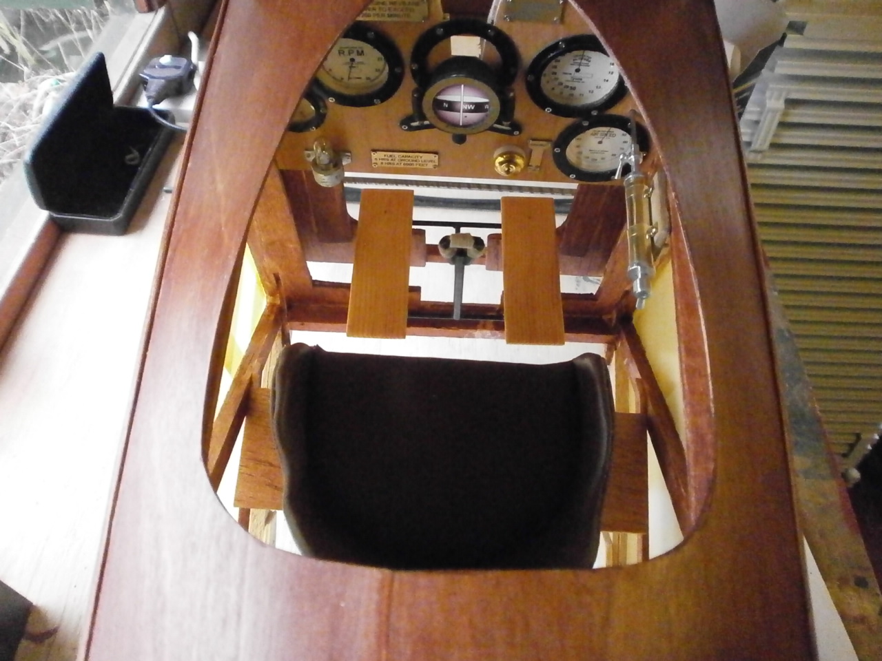
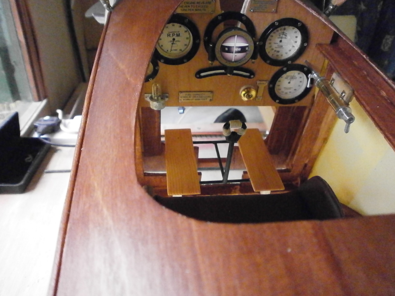
The following pictures showing the assembly now in place.
 |
 |
|
The pilot test fitted into position. The seat still needs gluing into position at this stage but before I do I need to make up the seat belt assembly. |
Below are a number of pictures showing the feed and collection shoots for the Vickers machine gun. These where both made using 1/64 ply which was then covered in aluminium sticky tape. Once the tape is applied, it is sanded to give it a burnished effect with fine wet and dry paper.
 |
 |
 |
 |
 |
 |
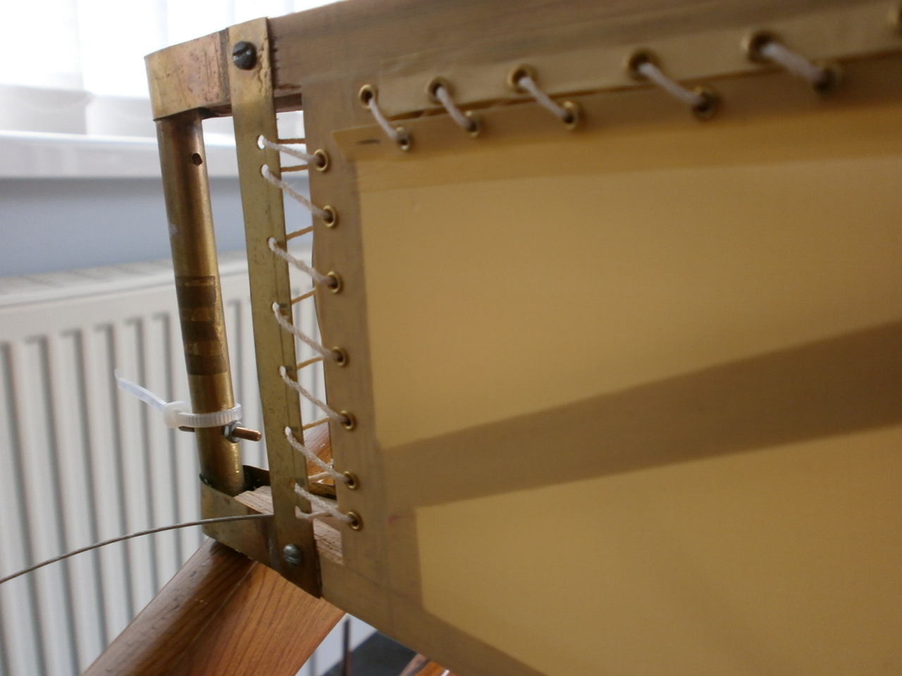
The following pictures showing the cockpit
edging.
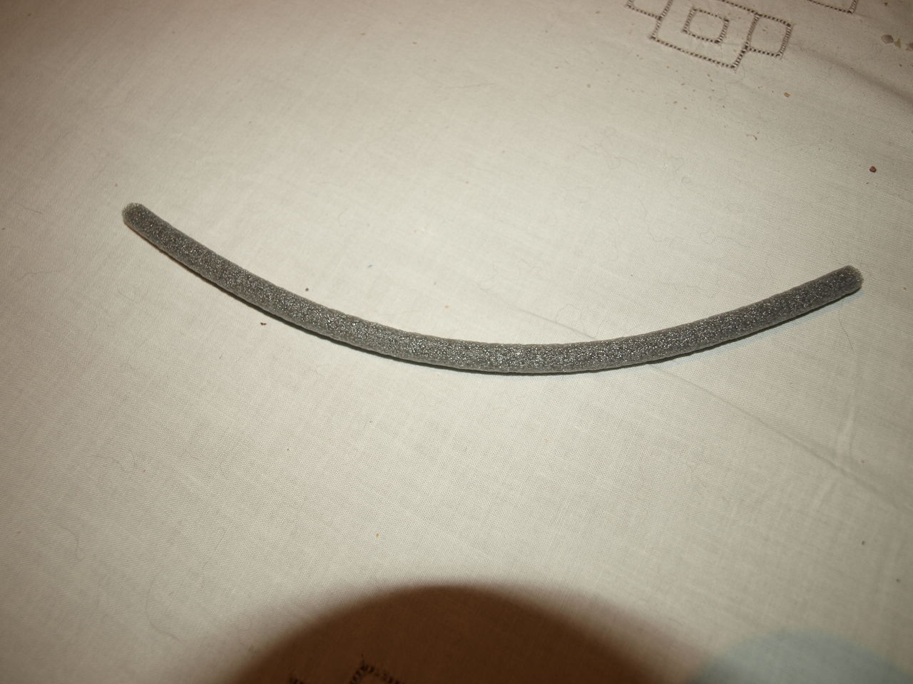 This is made from foam piping 8mm diameter which is cut horizontally along its required length to depth of half its diameter. |
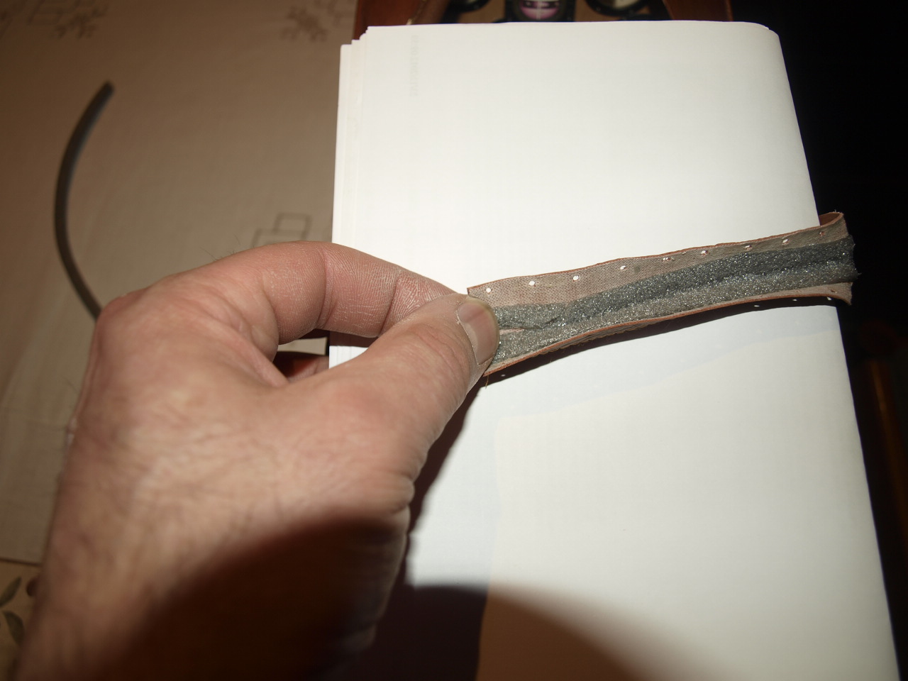 This is then glued to the imitation leather strip that has previously had a stitching seem run down its entire length |
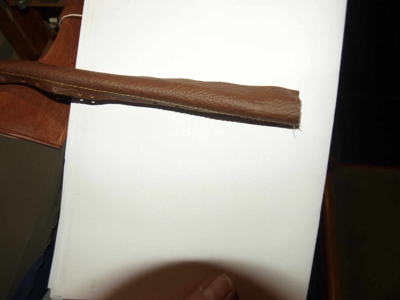 Once the dry a series of eyelet holes are punched along the outer edge of the leather (10mm spacing ) ready to take the brass eyelets. |
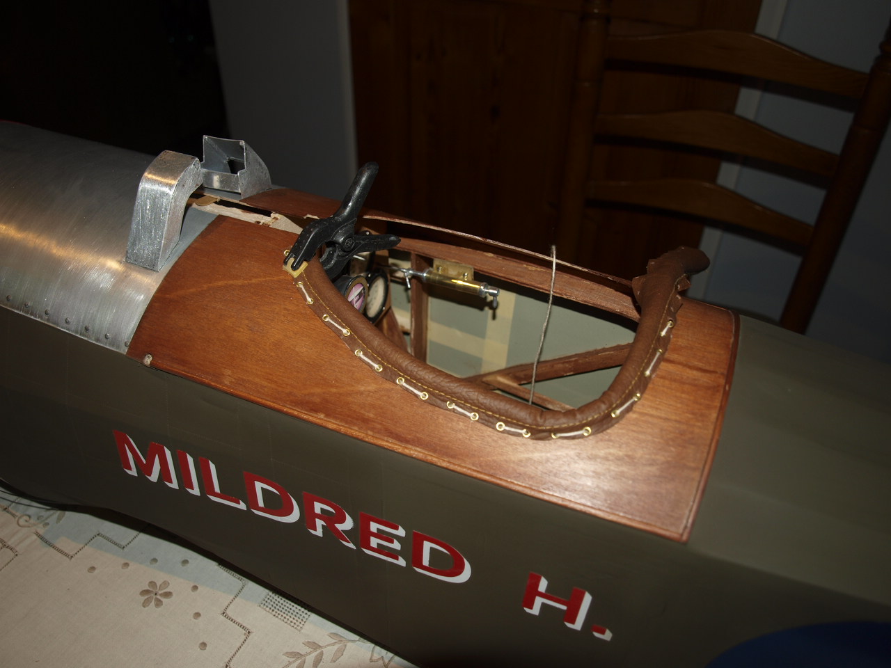 The edging is then offered up to the cockpit opening ensuring that the sliced foam sits either side of the ply. Once in place the eyelet holes act as a guide for drilling the holes through the ply cockpit decking that the brass eyelet and the securing thread we pass through. Once these are drilled out the securing thread is weaved in and out of the leather and ply holes, placing in the eyelets as you go from on side of the cockpit to the other. |
 Once all threaded up you then go back to the beginning and tighten up the thread ensuring also that the brass eyelets are sitting correctly in their correct hole locations. |
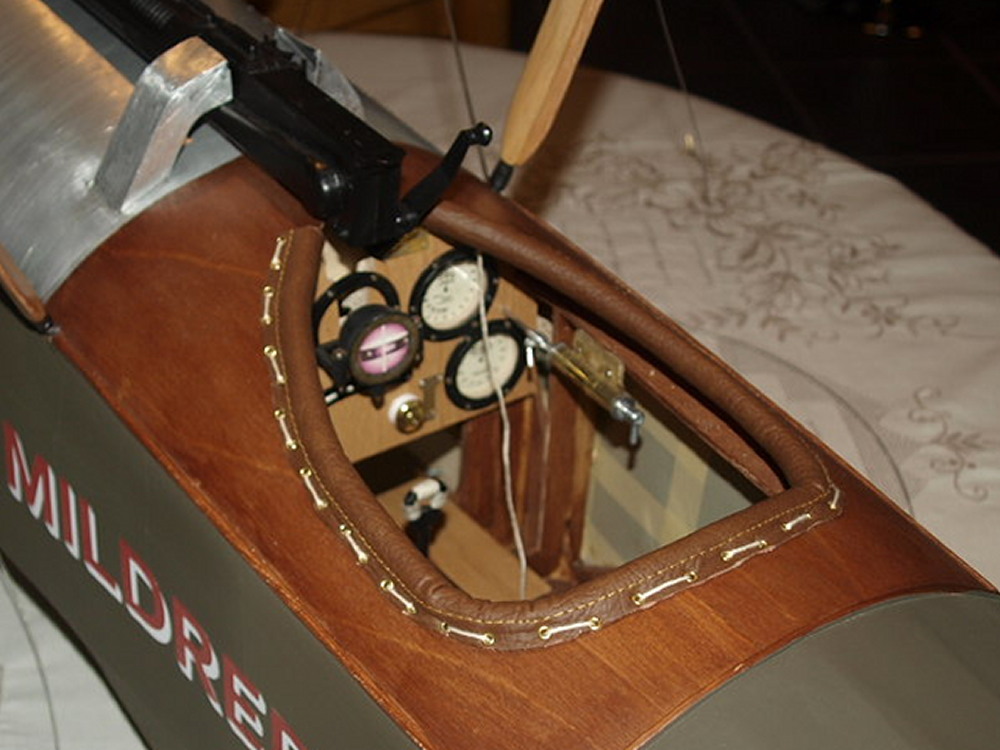 The finished result |