SE5A Fuselage Page 2
Having completed the main fuselage structure, the cowl has been made with all its panels and dummy engine blocks which i have covered on another page on this site. If you have not seen the cowl yet, see picture below.
|
|
With the cowl now
completed as far as we can go at this stage of the build, our attention
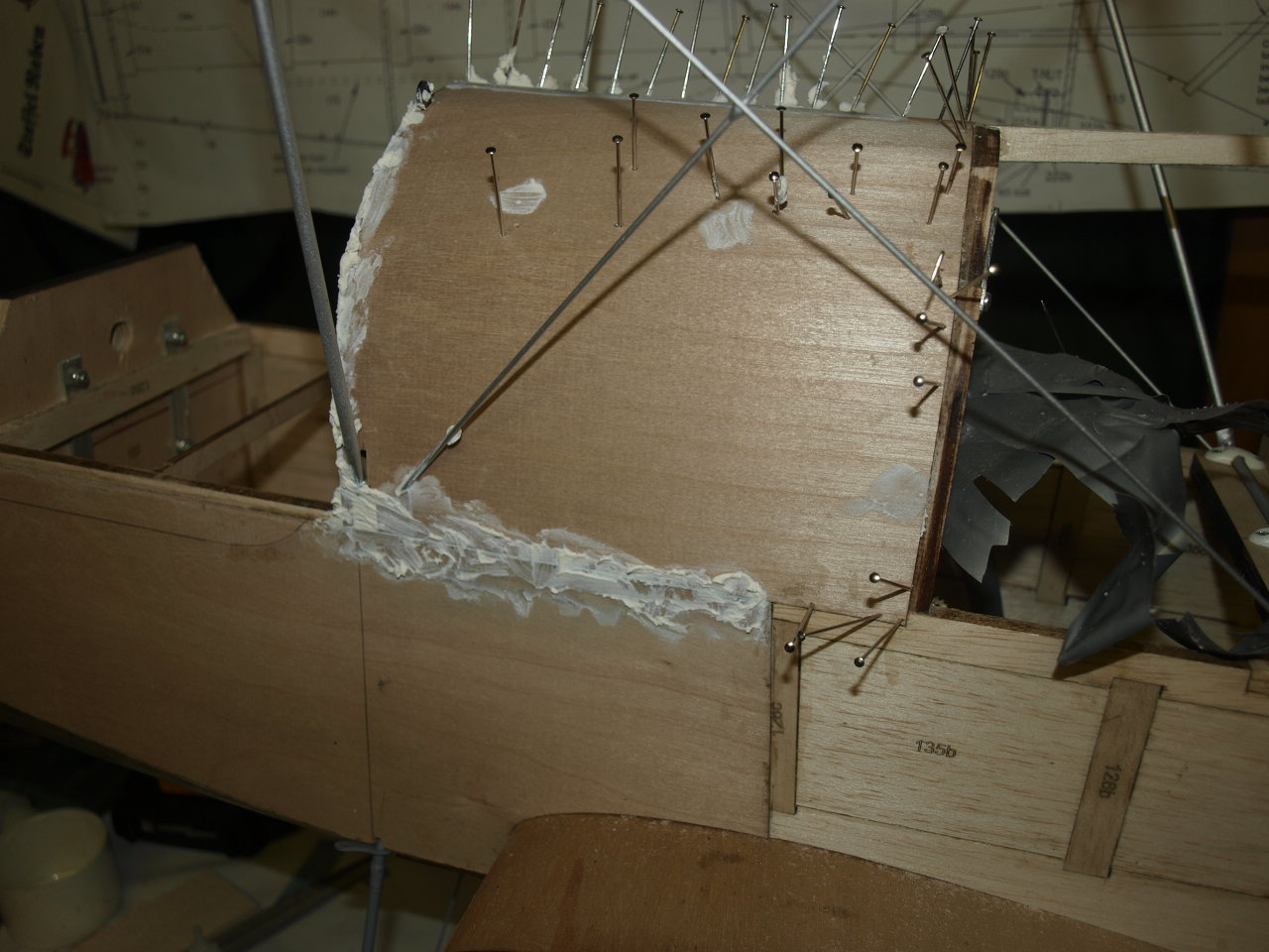
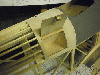
turned to the next panel along (fuel tank). This panel is going to be somewhat awkward
as the front part of the cabane struts are located in this area. This
means that the ply decking sheet will need to be cut as the struts protrude
out from it. Picture 2 below shows a balsa block that has to be glued into
position, where the Vickers Machine Gun exits the fuselage.
On the plans it
just shows the block glued to the former. We did not like this approach as
it seemed very flimsy. As you can see to improve the structural integrity of
this piece, we have added two stringers to the block and this assembly is
glued between the two formers.
 |
 |
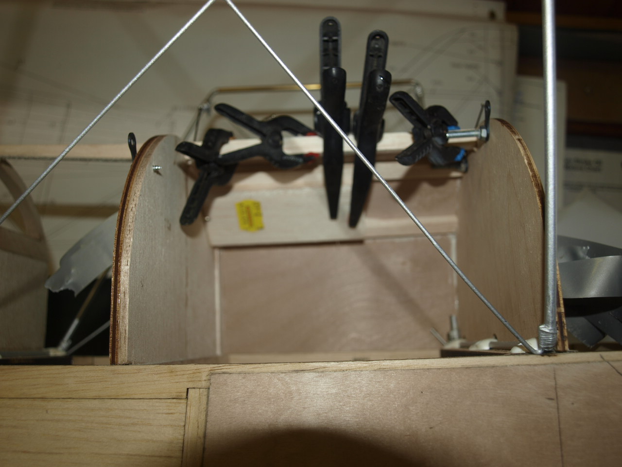
I would have liked to have sheeted this decking piece as one but due to the complexities of cutting the sheet around the carbains, decided to do the job in two halves. Picture one below shows the first half cut, glued and pined into position. Picture two shows the balsa block from the inside, note the clamps pulling down the ply deck sheet to it. It is important that the ply is fully adhered to this piece as there will be a need two sand a curved recess into this panel allowing correct alignment of the Vickers as it exits through the fuselage.
|
|
 |
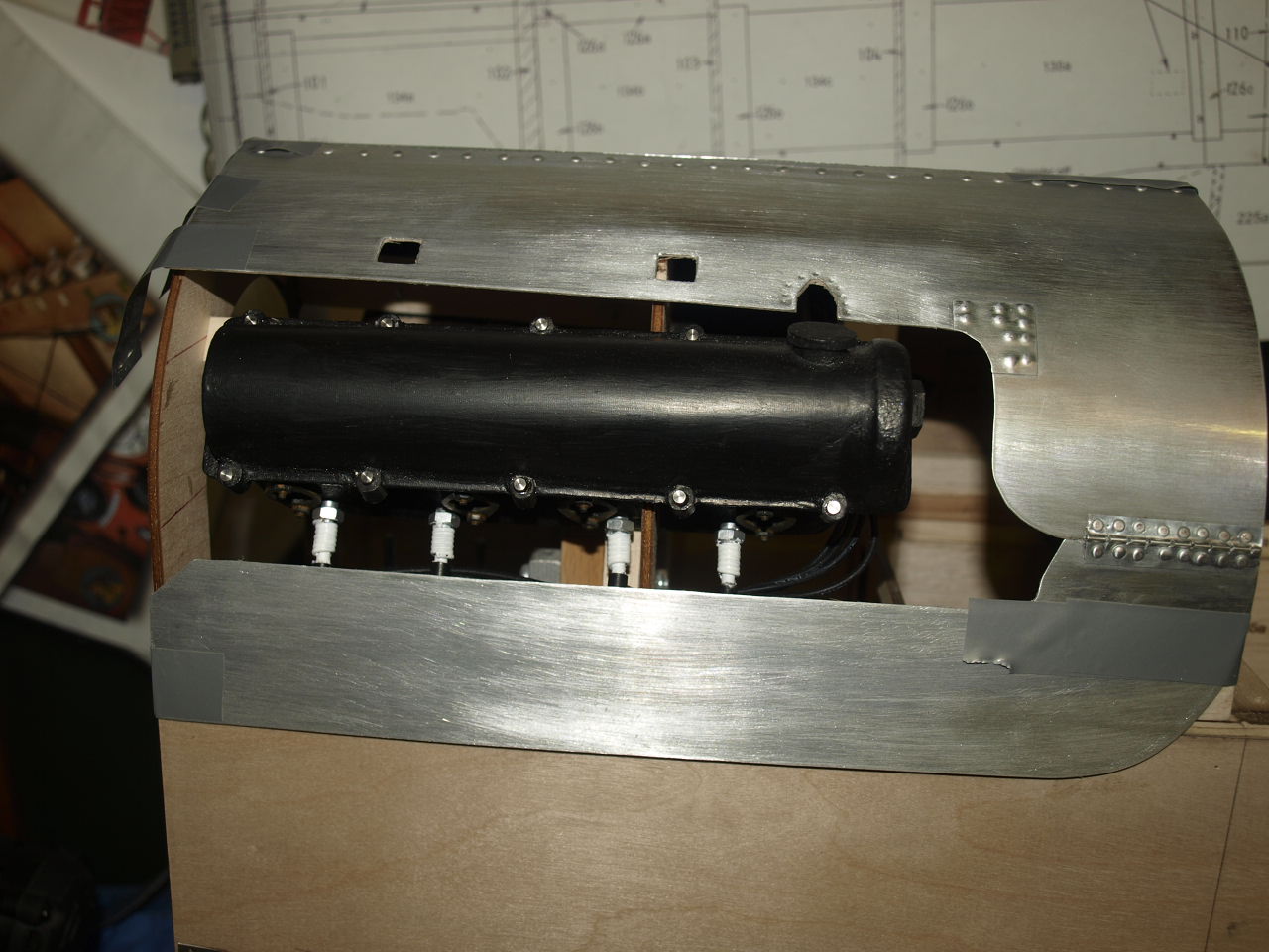
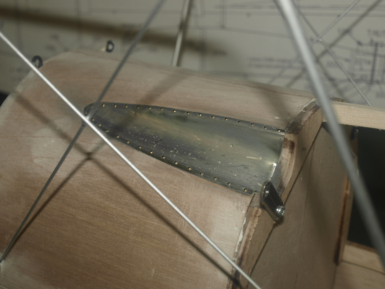
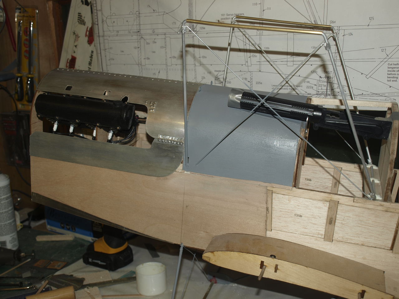
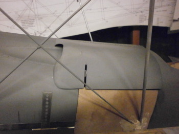
Once dry the recess is sanded
out to accommodate the gun and as can be seen from the first picture below a
litho plate fairing made up and glued and riveted into position
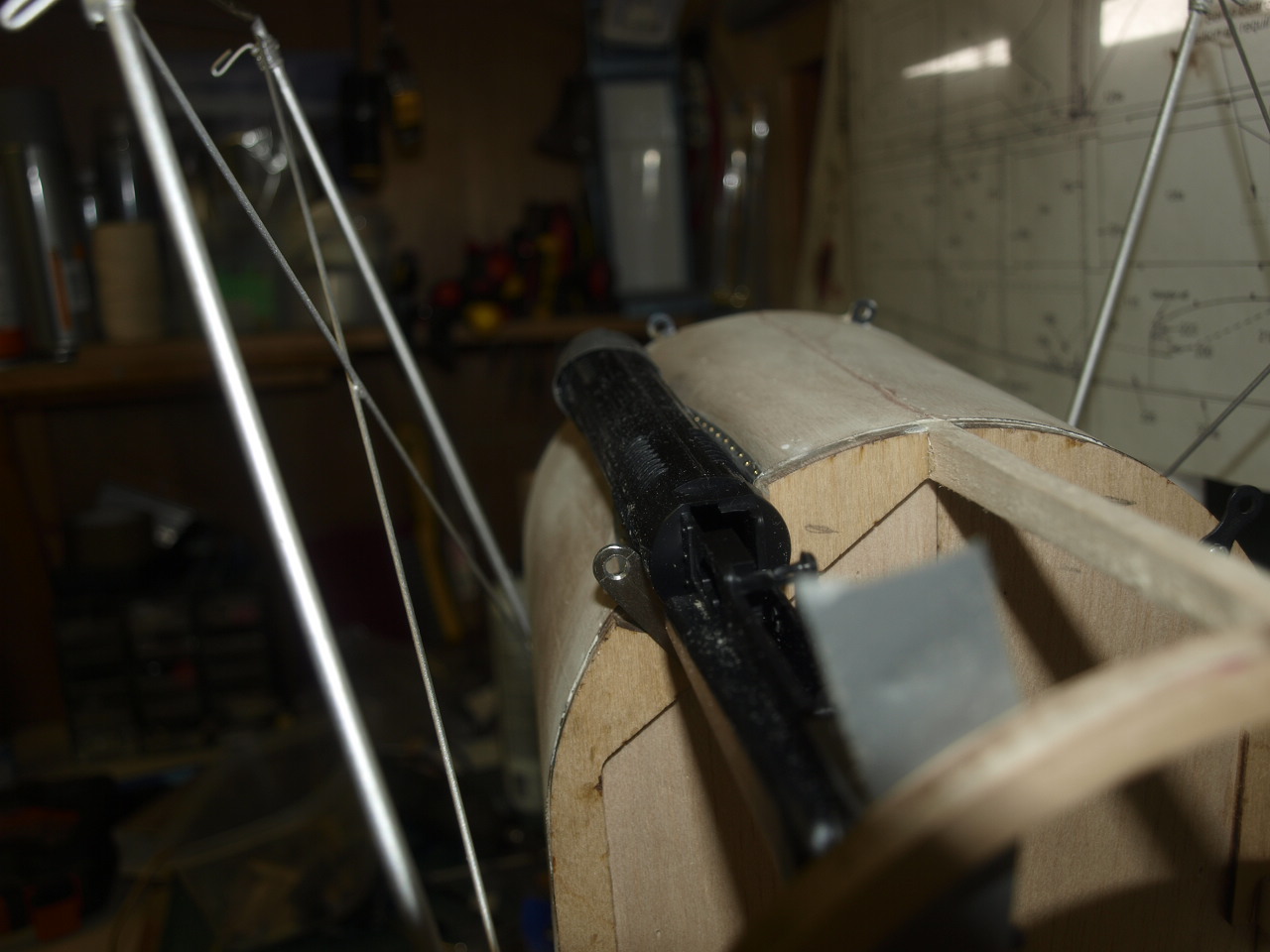
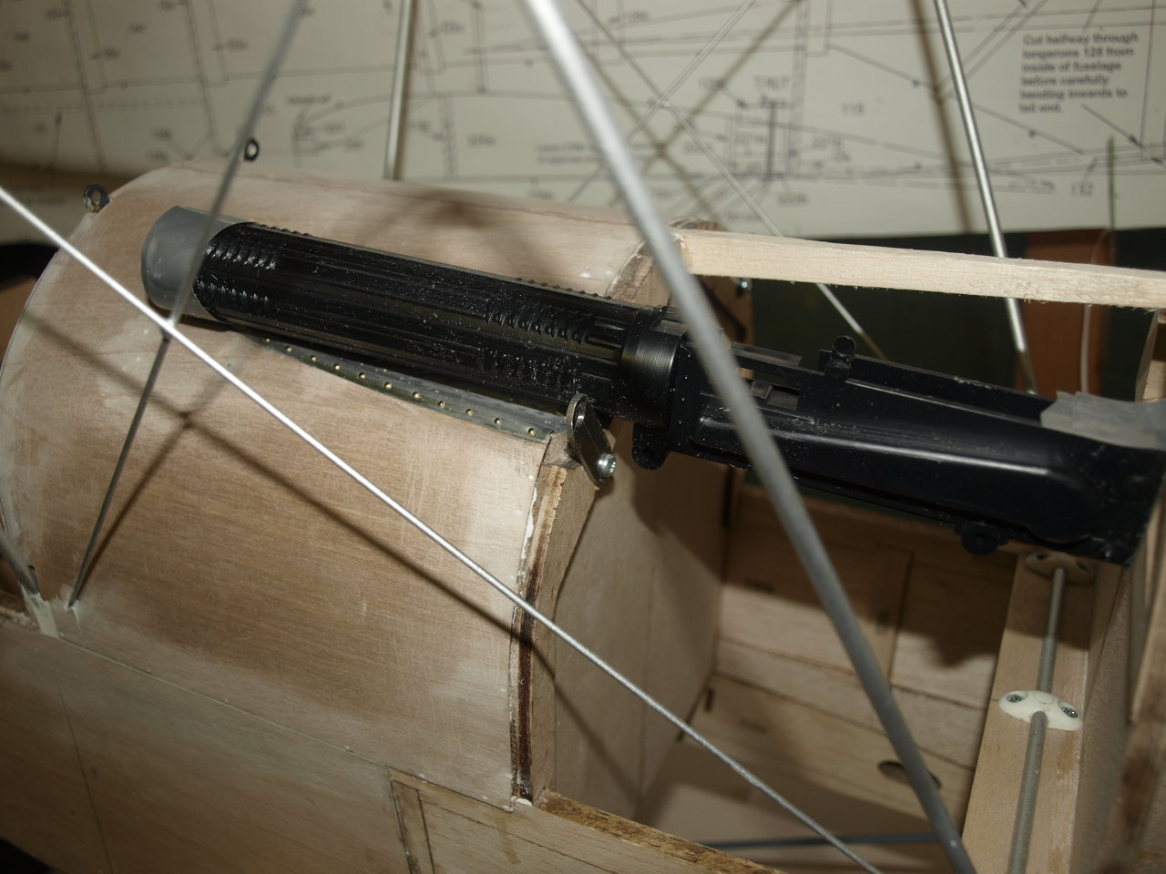
The next pictures shows the gun sitting in it correct position
 |
 |
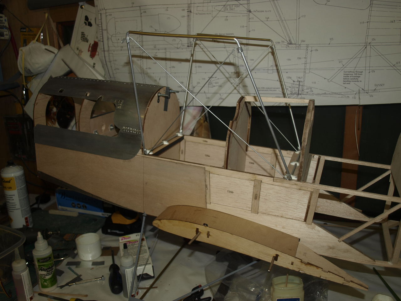
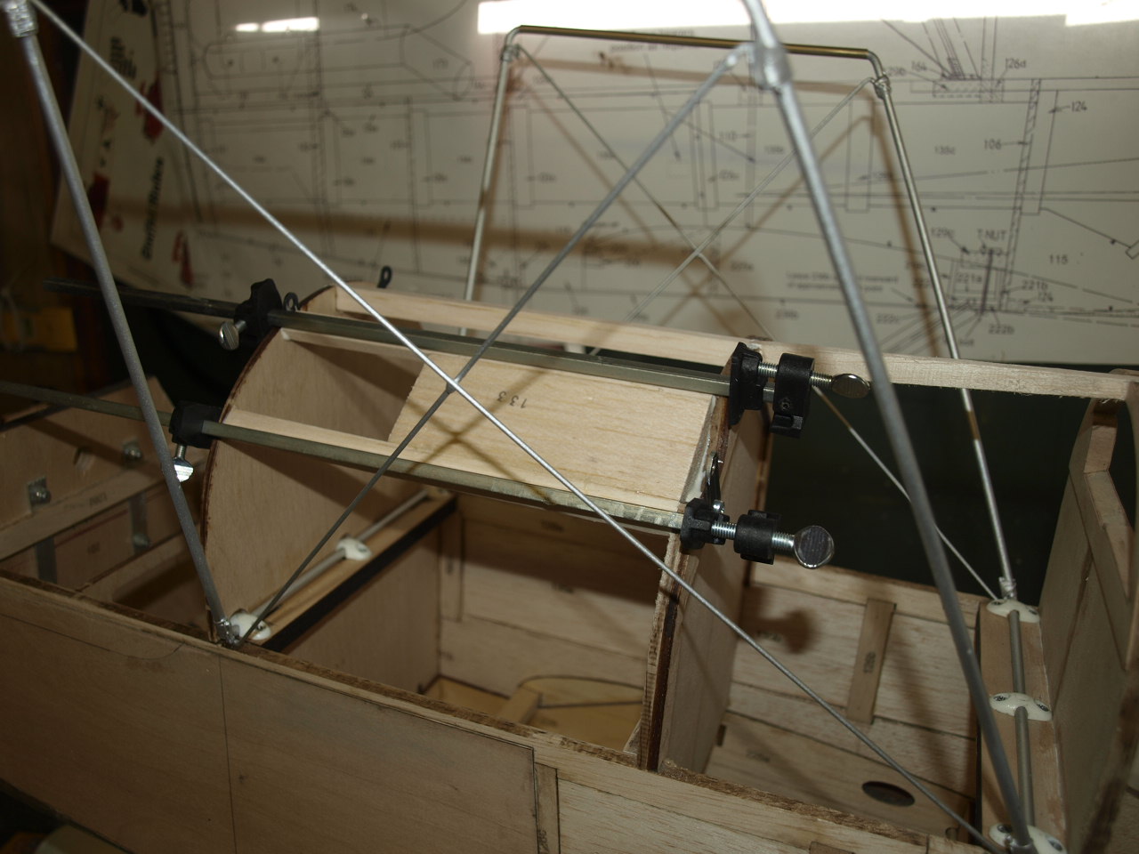
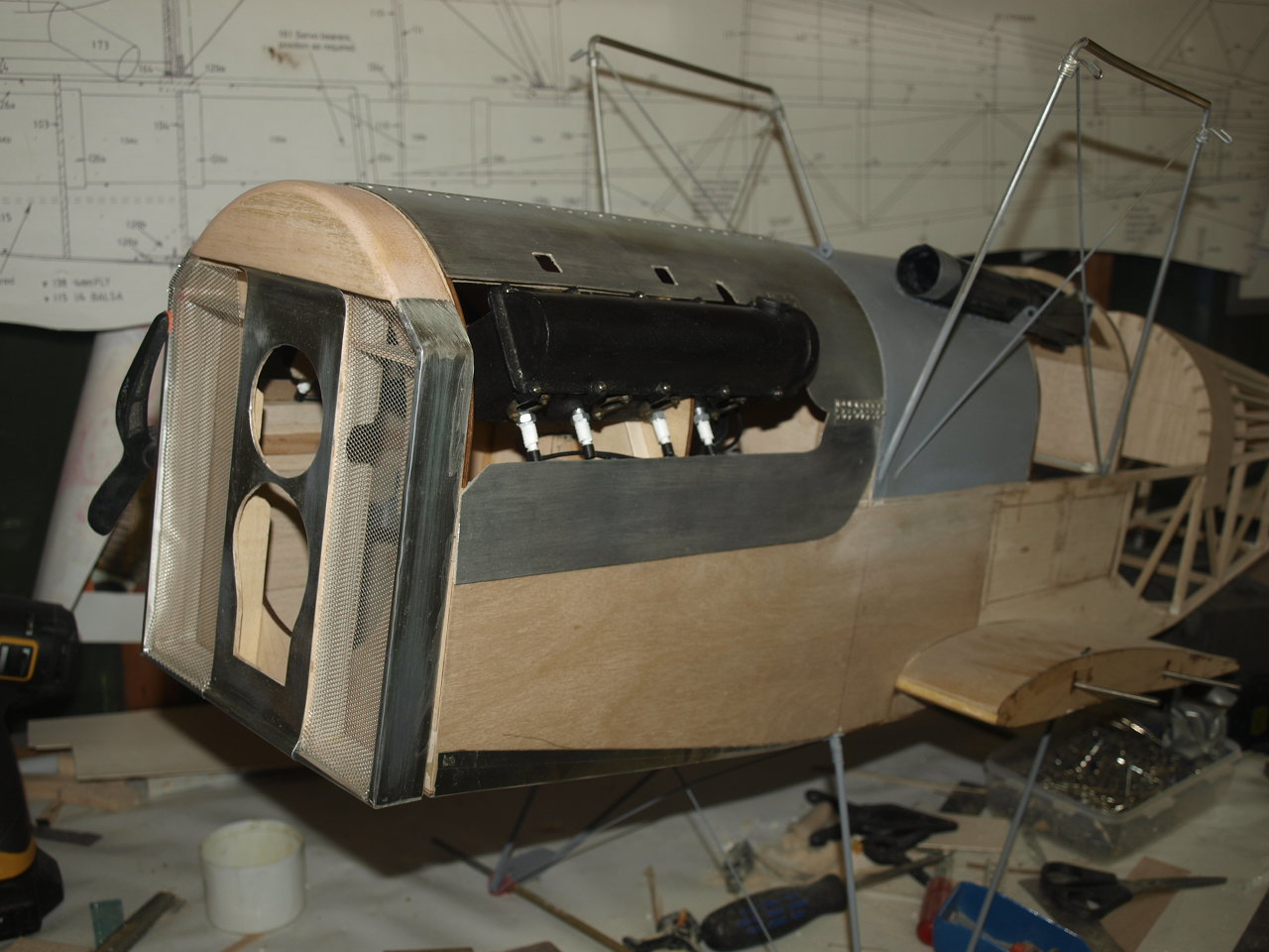
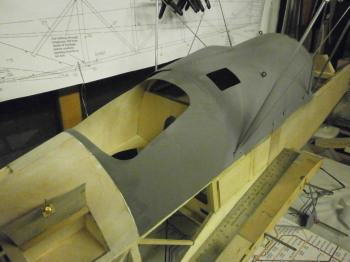
The following pictures showing the fuselage with Radiator, Cowl, Vickers and panel all in situ. She's starting to look like an SE5A now.
 |
 |
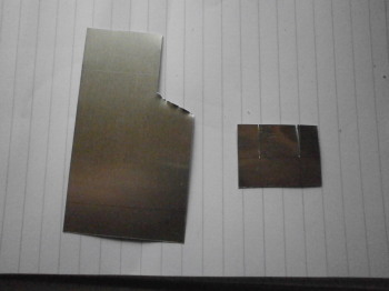
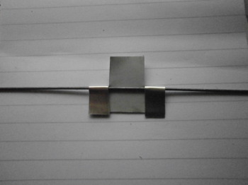
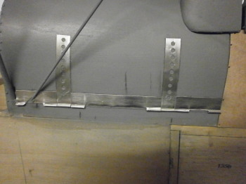
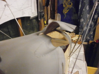
With the ply sheeting in place the next job is to make the scale hinging that would have secured the tank to the airframe. The hinging as can be seen from the series of pictures below is made up from Litho plate and fine piano wire.
As can be identified from the pictures below the Litho plate is marked out and each section cut where the bends will be introduced. Next the plate is heated up to soften it, this makes the plate easier to bend over the wire. The plate is then bent over the wire and forms the basic hinge.
 |
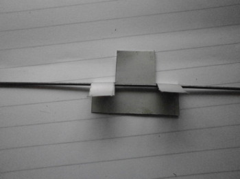 |
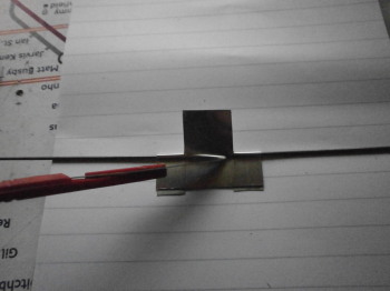
With the hinge formed the remaining tab left is cut away (pic 2)
 |
 |
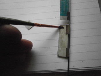
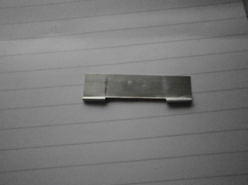
Now the bent tabs are glued down to the main hinge body with heavy duty contact adhesive. The second picture shows the final result.
 |
 |
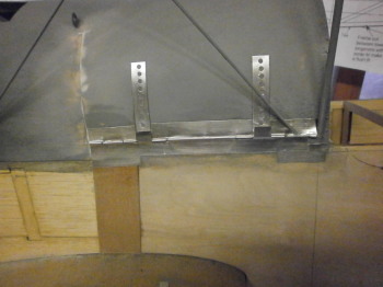
With all the hinge components made up the piano wire is passed through them and the whole assembly offered into position and glued into place.
 |
 |
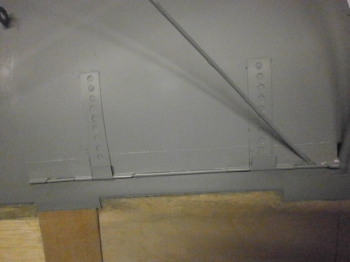
The n ext picture showing the assembly undercoated. The next job is to add the rivets to this assembly which will further bring it to life
 |
hinge riveted image to come |
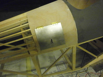
Below are a couple of pictures showing the rear storage hatch and the Vickers access hatch.
 |
 |
 |
 |
Picture showing the now installed cockpit decking
 |
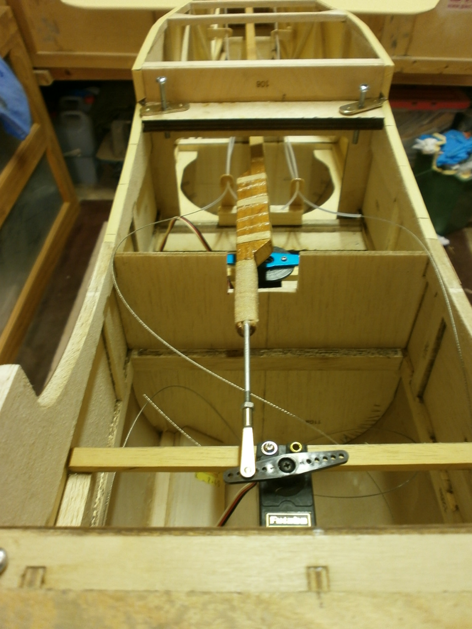
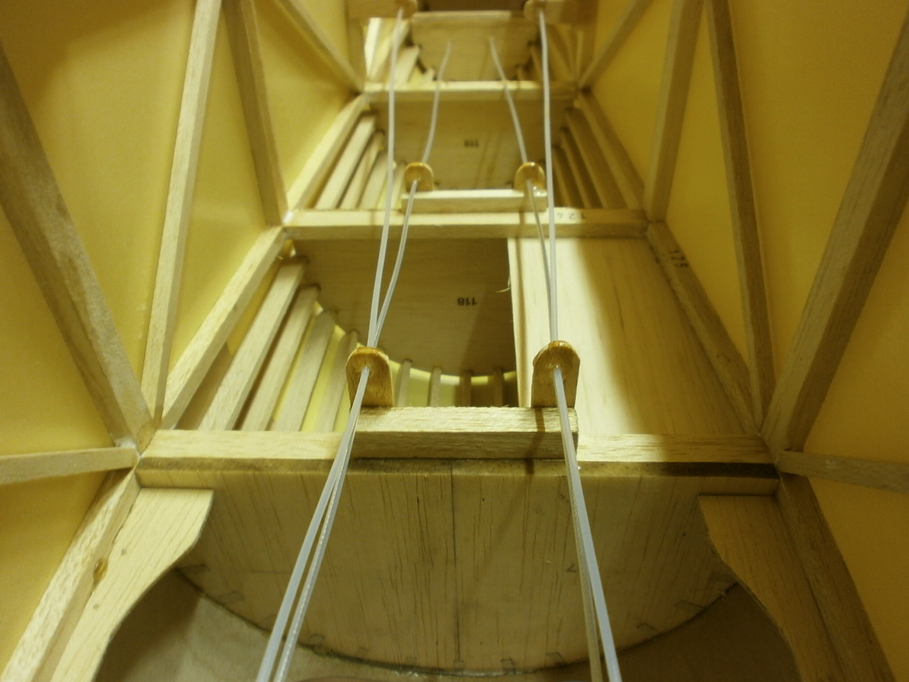
The next pictures below show the now made and elevator pushrod and closed loop wire guides installed.
Note: in the first picture, that the elevator pushrod has been made with an offset which ensure a straight run from the servo to the elevator linkage.
As you may have noticed the fuselage top and sides have been covered at this point. This will now allow me to concentrate on applying the stitching that runs along its sides. The method used to achieve this will be the same as that used on the Sopwith Pup
 |
 |
Stabiliser Elevator Build
Fuselage page
Fin & Rudder Build
Wing Build Bottom
Wing Retaining
System
SE5A Full size detail gallery
Landing gear
SE5A Cowl
TAIL ASSEMBELY